| Minimoog Voyager VX-351 CV Expander Output Adapter Installation Disclaimer: This modifcation risks voiding the warranty, damaging your Minimoog Voyager, and personal injury. If you are not adequately trained in electronics, do not attempt this on your own. Refer servicing to qualified Personnel Only! This page is not authorized by Moog Music, Inc. |
 |
|||
|
|
||||
| These items are required for installing the Output Adapter. | Peronal grounding system or static free environment A large, well lit, workbench A regular Philips head screwdriver - NOT a powered Driver Thin Soft Cloths (2) Output Adapter (Supplied with the VX-351 CV Expander package) |
|||
|
|
||||
| Before You Begin
DISCONNECT POWER FROM THE MINIMOOG VOYAGER! Do Not attempt to install the Output Adapter with the unit powered on! Anyone who does this is an Idiot! Static Electricity will damage Internal Components. Before you start, make sure you are grounded or discharged. |
DISCONNECT POWER FROM THE MINIMOOG VOYAGER! | |||
|
|
||||
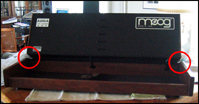
| 1. Getting Started
Set the Minimoog Voyager on your workspace with the Back Panel facing you. Lift the Front Panel Up and hold it at 90° perpendicular to the body. Insert the soft cloths in the crevice between the wooden sides of the Front Panel and the wooden board above the keyboard. The Side Panels could pinch the top board leaving an unwanted dent. If possible, find someone to hold the Front Panel vertical. This works best! |
|
|||
|
|
||||
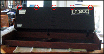
| 2. Removing the Screws
There are 5 Screws that fasten the rear door of the Front Panel. While Holding the Front Panel vertically, unscrew the Five screws using the Philips head Screwdriver. Set the Screws to the side within arms reach. |
|
|||
|
|
||||
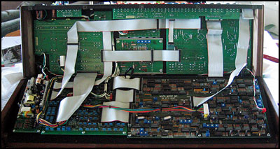
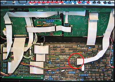
| 3. Open the Rear Panel
Gently let the Front Panel tip foward and make certain that you don't put pressure down causing the dings. Slowly - Very Slowly open the hinged back door, and lower the rear panel down into the case. You will see circuitboards fastened down to the rear panel and plenty of ribbon cables connecting these boards to the Controller Circuitboards on the front panel. |
|
|||
|
|
||||
| 4. Find the Accessory Port Connector
Locate the Accessory Port ribbon cable connector on the large circuitboard. It's on the middle of the board just to the right of the "Moog Music Inc." label Gently Extract the Connector from the circuitboard. Move the ribbon connector to the side. |
|
|||
|
|
||||
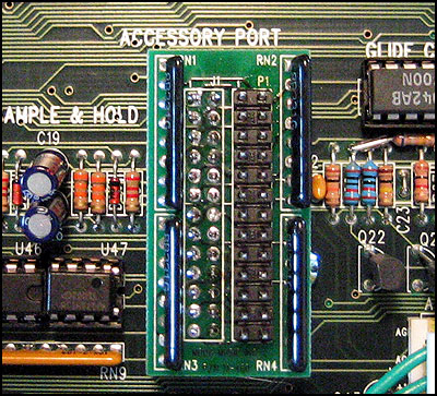
| 5. Install the Output Adapter
The Output Adapter should be positioned vertically with the ribbon connector P1 at the top right. Make sure that the connector on the bottom side is aligned with the connector socket. With firm pressure, insert the Output Adapter into the Ribbon connector socket on the circuit board. |
|
|||
|
|
||||
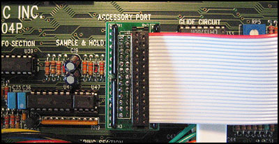
| 6. Reconnect the Ribbon Cable
Position the Ribbon Cable connector over the Output Adapter. Make sure the pins on the Output adapter line up with the female connector. Carefully press down and seat the ribbon cable to the Output Adapter. The Adapter has now been installed! |
|
|||
|
|
||||
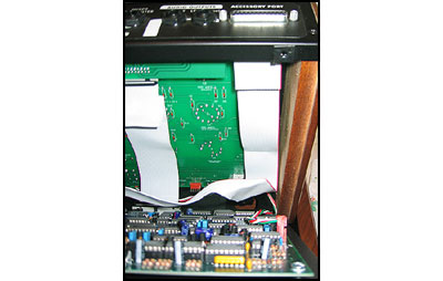
| 7. Closing the Front Panel Case
Close the Rear Panel Slowly, and pay attention that the ribbon cables do not pinch. If you have fully extended the ribbon cable to the accessory port, make certain that it is folded back up before you close the case. If the case does not close all the way, check for other cables or wires that might be pinched between components and the circuit boards. DO NOT FORCE THE CASE CLOSED! It should close without any pressure. If it doesn't then check for spots where the cable is being pinched. |
|
|||
|
|
||||
| 8. Replacing the Screws
While holding the Front Panel vertically, replace the 5 screws and tighten them with medium torque. Do not over-torque the screws. Remove the Soft Cloths and set the Front Panel back down into the case. |
|
|||
|
|
||||
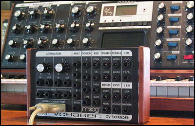
| 9. Connect the VX-351
Connect the 25 pin D-connector from the Minimoog Voyager to the VX-351 and start routing CV signals back into the Voyager or to other Analog Devices! You should test out the VX-351 by patching the Filter cutoff frequency on the Voyager to the various outputs on the VX-351. |

|
|||
|
|
||||
|
|
©1997-2004 Kurt Kurasaki |
|||